1. General Introduction
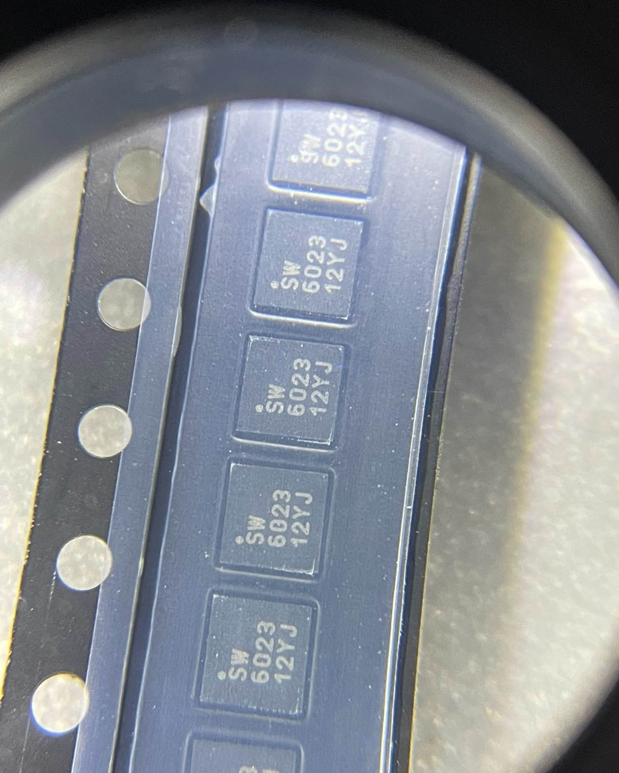
The RFSW6023TR7 is a radio – frequency (RF) switch integrated circuit designed for various wireless communication applications. It is engineered to provide efficient signal routing and switching capabilities in RF systems, enabling seamless communication between different components.
2. RF Signal Switching
2.1 Single – Pole, Double – Throw (SPDT) Configuration
- The RFSW6023TR7 typically features a single – pole, double – throw (SPDT) switch configuration. This means it has one input port and two output ports. An input RF signal can be directed to either of the two output ports based on the control signals applied to the chip. For example, in a wireless transceiver, the SPDT switch can be used to route the transmitted RF signal from the power amplifier to the antenna during the transmission mode and, during the reception mode, route the received RF signal from the antenna to the low – noise amplifier.
2.2 High – Frequency Operation
- It is designed to operate at high frequencies, making it suitable for modern wireless communication standards. It can handle RF signals in the frequency range relevant to applications such as cellular networks (e.g., GSM, LTE, 5G), Wi – Fi (2.4 GHz and 5 GHz bands), and Bluetooth. The ability to operate at these high frequencies is crucial as it allows for the efficient handling of the high – speed data – carrying signals used in these wireless communication technologies.
3. Low Insertion Loss and High Isolation
3.1 Low Insertion Loss
- The chip offers low insertion loss when the RF signal is passing through the switch. Insertion loss refers to the amount of signal power that is lost as the signal travels from the input to the selected output port. A low insertion loss ensures that the integrity of the RF signal is maintained, minimizing signal degradation. In a wireless link, low insertion loss is essential for maximizing the range and signal quality. For instance, in a long – range Wi – Fi bridge application, minimizing insertion loss in the RF switch helps in ensuring that the transmitted signal reaches the receiver with sufficient strength.
3.2 High Isolation
- It also provides high isolation between the non – connected ports. Isolation is the measure of how well the switch prevents the leakage of the RF signal from the input to the non – selected output port. High isolation is critical in preventing crosstalk between different signal paths. In a multi – channel wireless communication system, high isolation in the RF switch ensures that signals on one channel do not interfere with those on other channels, improving the overall performance and reliability of the system.
4. Control Interface
4.1 TTL/CMOS Compatible Control
- The RFSW6023TR7 is equipped with a control interface that is compatible with Transistor – Transistor Logic (TTL) and Complementary Metal – Oxide – Semiconductor (CMOS) logic levels. This compatibility allows for easy integration with digital control circuits, such as microcontrollers or field – programmable gate arrays (FPGAs). A simple digital control signal, typically a logic high or low, can be used to switch the RF signal between the two output ports. For example, a microcontroller can be programmed to send control signals to the RF switch based on the mode of operation of the wireless device, such as switching between different communication channels or between transmit and receive modes.
4.2 Fast Switching Speed
- The chip has a fast switching speed, which is important for applications that require rapid changes in signal routing. It can quickly respond to the control signals and switch the RF signal from one output port to the other within a very short time frame. In a wireless communication system that needs to adapt to changing network conditions or user demands in real – time, the fast switching speed of the RF switch enables seamless transitions between different operating modes or signal paths.
5. Power Handling and Thermal Considerations
5.1 Power Handling Capability
- The RFSW6023TR7 is designed to handle a certain amount of RF power. It can withstand the power levels associated with typical RF transmitters in wireless communication systems. The power handling capability ensures that the switch can operate reliably without being damaged by the high – power RF signals. For example, in a base station for a cellular network, the RF switch needs to handle the high – power signals transmitted to cover a wide area, and the RFSW6023TR7’s power handling ability makes it suitable for such applications.
5.2 Thermal Management
- It also takes into account thermal management. During operation, the chip may generate heat due to the handling of RF power. To ensure reliable operation, it is designed with features to dissipate this heat effectively. This may include a specific package design that allows for good heat transfer or internal thermal protection mechanisms. In high – power applications, proper thermal management is crucial to prevent overheating, which could lead to performance degradation or even damage to the chip.
6. Application Areas
6.1 Wireless Transceivers
- In wireless transceivers, the RFSW6023TR7 is used for switching between the transmit and receive paths. It enables the efficient utilization of the antenna for both transmitting and receiving RF signals. This is essential in devices such as smartphones, tablets, and wireless access points, where the ability to switch between transmit and receive modes quickly and with low signal loss is crucial for good communication performance.
6.2 RF Test and Measurement Equipment
- In RF test and measurement equipment, the chip can be used to route RF signals to different components for testing purposes. For example, it can be used to switch between different signal sources or to direct the output of a device under test to different measurement instruments. The low insertion loss and high isolation of the switch are beneficial in ensuring accurate test results.
6.3 Antenna Switching Systems
- In antenna switching systems, the RFSW6023TR7 can be used to select between different antennas. In a multi – antenna wireless system, such as a Multiple – Input Multiple – Output (MIMO) system, the switch can be used to route the RF signal to the most appropriate antenna based on factors like signal strength, interference, and communication requirements. This helps in optimizing the performance of the wireless link.





Leave a Reply