- Signal Isolation Function
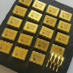
- One of the core functions of the GH281-4 optocoupler is signal isolation. In electronic circuits, it can electrically isolate the input signal from the output signal. For example, in an industrial control circuit, the signals from the control part (such as a microcontroller) may be affected by external interference sources (such as electromagnetic interference generated by high-power motors). The optocoupler transmits the control signal through an optical signal, making the input side (the control signal end) and the output side (the controlled signal end) completely electrically isolated. The isolation voltage can reach several thousand volts. In this way, even if the input side is interfered with, it will not directly affect the signals on the output side, thus improving the anti-interference ability and stability of the entire circuit.
- This isolation function is also very important for signal transmission between circuits with different potentials. For instance, in a complex system that has both digital circuits (operating at a low voltage, such as 3.3V or 5V) and analog circuits (which may operate at a relatively high voltage, such as ±12V), the optocoupler can safely transmit the control signals from the digital circuits to the analog circuits, preventing short circuits and mutual interference between different potentials.
- Signal Transmission Function
- It can effectively transmit signals. Its working principle is based on photoelectric conversion. When an electrical signal is applied to the input side (the light-emitting diode end), the light-emitting diode emits light, and the optical signal passes through the internal transparent medium (such as transparent packaging material) and shines on the output side (the phototransistor end). After receiving the optical signal, the phototransistor generates a corresponding electrical signal output. For example, in a simple digital signal transmission circuit, if the electrical signal on the input side is a digital pulse sequence (such as high and low level signals representing binary data), the light-emitting diode will flash according to this pulse sequence, and the phototransistor on the output side will correspondingly generate a pulse sequence with the same frequency and duty cycle, thus realizing the transmission of the signal from the input side to the output side.
- For analog signal transmission, although the linearity of the optocoupler is limited, it can also transmit analog signals within a certain range. For example, in an audio signal transmission circuit, the change in the input-side audio voltage signal will cause a change in the light intensity of the light-emitting diode. The phototransistor on the output side generates a corresponding change in the electrical signal according to the change in the received light intensity, thus realizing the transmission of the audio signal. However, appropriate compensation and calibration of the output signal may be required to improve linearity.
GH281-4
Dynasty Digital is deeply engaged in the electronic industry supply chain services, with the mission of empowering global electronic enterprises to operate efficiently. It integrates core resources and professional capabilities to provide global customers with full-chain services including electronic product information, procurement, quality control, and supply chain optimization, building a connecting bridge between high-quality Chinese electronic resources and the global market.
Leave a Comment


