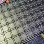
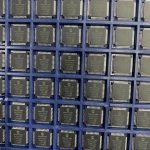
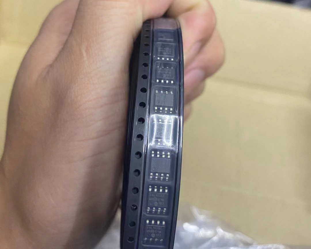
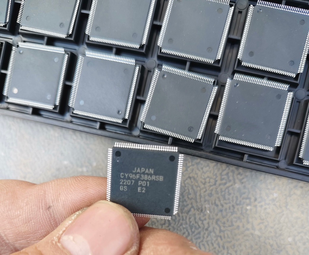
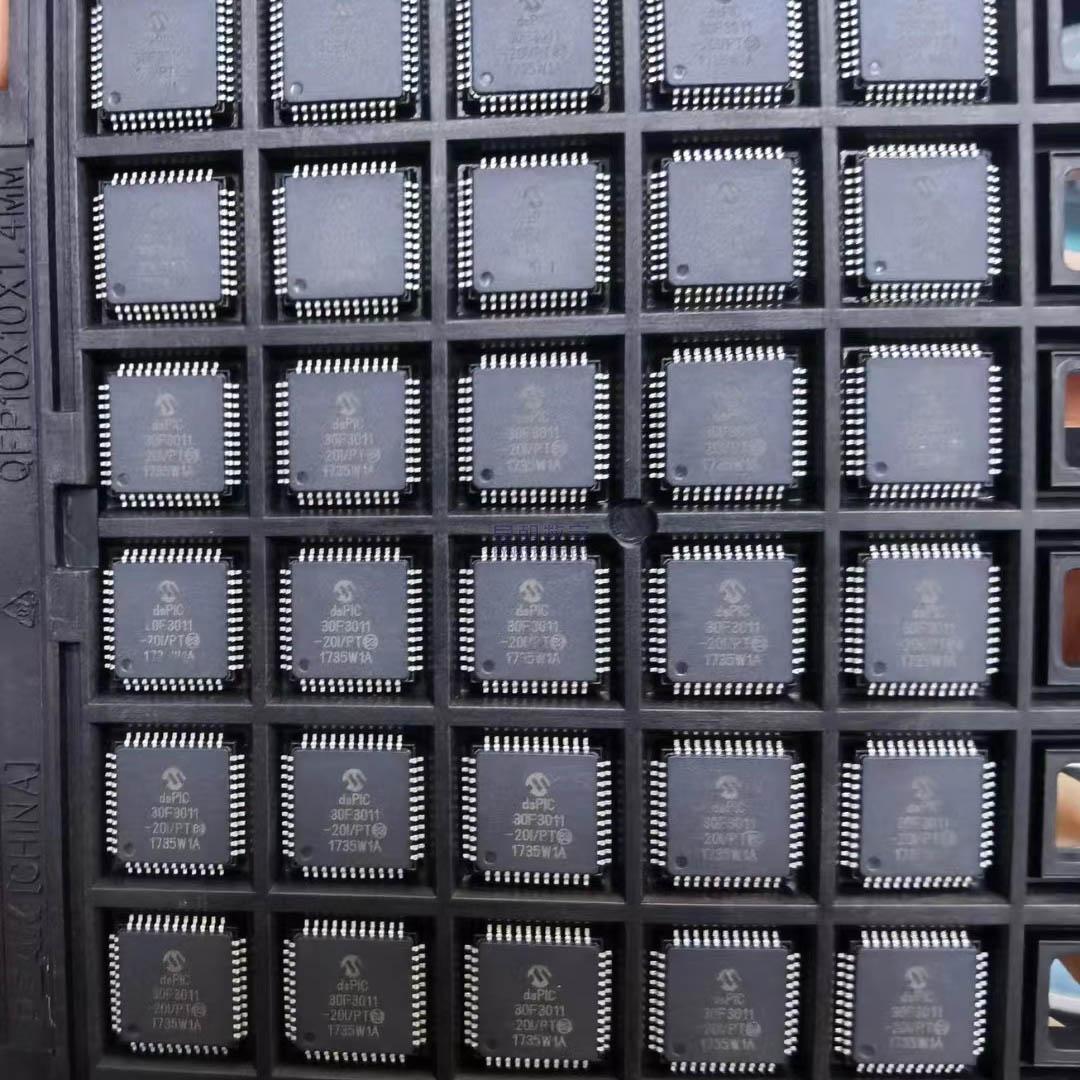
The DSPIC33EP128GS804 – I is a microcontroller with integrated digital signal processing (DSP) capabilities.
CPU and Instruction Execution
Central Processing Unit (CPU): It has a high – performance CPU that executes a wide range of instructions. The CPU can handle arithmetic operations like addition, subtraction, multiplication, and division. It also manages logical operations such as AND, OR, and NOT, as well as control – flow operations including loops and branches.
Instruction Set: The instruction set includes DSP – specific instructions. These are designed to efficiently perform digital signal processing tasks. For example, it can execute instructions for filtering algorithms, Fourier – transform – related operations, and other DSP – centric calculations with high speed and precision.
Memory Architecture
Program Memory: The microcontroller contains program memory, typically Flash memory. This is where the executable code for the device’s applications is stored. The program memory can be programmed and reprogrammed, allowing for firmware updates and different application – specific code implementations.
Data Memory: It has data memory for storing variables, buffers, and intermediate results during program execution. The data memory includes different types such as SRAM (Static Random – Access Memory), which provides fast access to data for the CPU to manipulate.
EEPROM (if available): Some versions may have Electrically Erasable Programmable Read – Only Memory (EEPROM). This is useful for storing non – volatile data such as configuration settings, calibration values, or user – specific data that needs to be retained even when the power is off.
Digital Signal Processing (DSP) Features
Multiplier – Accumulator (MAC) Unit: It features a powerful MAC unit. This is crucial for DSP algorithms as it allows for efficient multiplication and accumulation operations. In digital filtering applications, for example, the MAC unit can quickly calculate the filtered output based on the filter coefficients and input samples.
DSP Engine: The DSP engine provides hardware – supported DSP functionality. It can handle complex DSP tasks such as high – order filtering, spectral analysis, and adaptive signal processing with enhanced speed and accuracy compared to software – only implementations.
Peripheral Interfaces
General – Purpose Input/Output (GPIO): The device has GPIO pins that can be configured as inputs or outputs. These pins can interact with external devices such as switches, LEDs, sensors, and actuators. The GPIO allows for bidirectional communication with the external environment, enabling the microcontroller to read external signals and send control signals.
Analog – to – Digital Converter (ADC): It includes an ADC to convert analog signals from sensors (e.g., temperature sensors, light sensors, or pressure sensors) into digital values. The ADC has a specific resolution and sampling rate, ensuring accurate conversion of the analog input for further processing by the CPU.
Digital – to – Analog Converter (DAC) (if available): Some configurations may have a DAC, which converts digital signals into analog format. This is useful for generating analog output signals such as audio signals or control voltages for analog – controlled devices.
Serial Communication Interfaces: The microcontroller supports various serial communication protocols. These include UART (Universal Asynchronous Receiver/Transmitter), SPI (Serial Peripheral Interface), and I2C (Inter – Integrated Circuit). These interfaces enable the microcontroller to communicate with other electronic devices such as sensors, displays, and communication modules.
Timer and Counter Modules
Timers: Built – in timers are available for timing – related applications. They can generate periodic interrupts, which are useful for tasks such as updating displays at regular intervals, sampling analog inputs, or generating PWM (Pulse – Width Modulation) signals for motor control or power – regulation applications.
Counters: The counters can count external events such as pulses from an encoder. They are applicable in speed – measurement and position – detection applications, among others.
Interrupt System
Interrupt Controller: The DSPIC33EP128GS804 – I has an interrupt controller that manages and prioritizes interrupts. Interrupts can originate from external pins, internal peripherals, or software – generated events. The interrupt controller ensures that the most critical interrupts are serviced first, enabling efficient handling of asynchronous events.
Interrupt Service Routines: When an interrupt occurs, the CPU jumps to the corresponding interrupt service routine. These routines handle the specific event that caused the interrupt, such as processing an ADC conversion result or responding to an external device’s request.
Power Management
Power – Down Modes: The microcontroller offers multiple power – down modes to reduce power consumption. These modes are useful in battery – powered applications or when the device is not actively performing tasks. The power – down modes can be controlled by software to optimize power usage.
Power – On Reset and Watchdog Timer: It includes a power – on reset circuit to ensure proper startup. A watchdog timer is also present to reset the device if the program malfunctions or gets stuck, thereby enhancing the system’s reliability.

