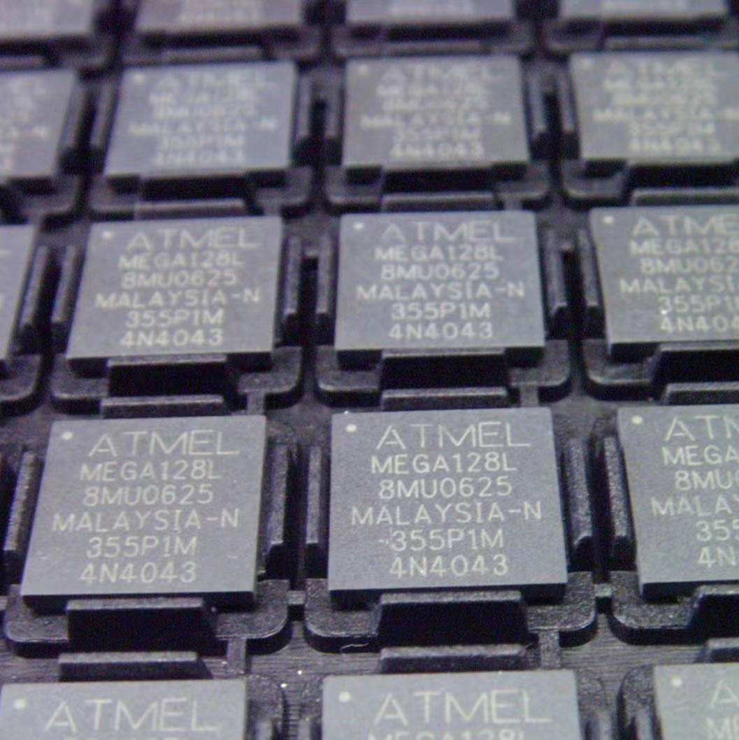
The DSPIC30F6010A – 30I is a microcontroller with digital signal processing (DSP) capabilities.
CPU and Processing
Central Processing Unit: It has a powerful CPU that executes instructions to perform arithmetic, logical, and data – transfer operations. The CPU can handle different data types and instructions, enabling complex programs to run.
Instruction Set: The microcontroller’s instruction set includes DSP – specific instructions. These instructions are designed to efficiently handle digital signal processing algorithms such as filtering, convolution, and Fourier – transform – related operations.
Data Manipulation: It allows for data manipulation in its internal data memory. The microcontroller can move, compare, and transform data, which is crucial for processing signals and handling application – specific data.
Memory System
Program Memory: The DSPIC30F6010A – 30I contains program memory (usually Flash memory). The program memory stores the executable code that defines the behavior of the microcontroller. It can be programmed and reprogrammed to update the firmware or change the application’s functionality.
Data Memory: There is data memory for storing variables, buffers, and intermediate results. The data memory is used during the execution of the program to hold data that the CPU operates on. It can include SRAM (Static Random – Access Memory) for fast access to data.
Memory Protection: The microcontroller may offer memory protection features. These features prevent unauthorized access to specific memory regions, which is useful in multi – tasking or security – sensitive applications.
Digital Signal Processing (DSP) Features
Multiplier – Accumulator: It features a high – performance multiplier – accumulator unit. This unit is essential for DSP algorithms as it allows for efficient multiplication and accumulation of data, which is common in operations like digital filtering and correlation.
DSP Engine: The DSP engine provides the necessary hardware support for running DSP algorithms quickly. It can handle tasks such as signal filtering with high – speed and accuracy, enabling the microcontroller to process real – time digital signals effectively.
Peripheral Interfaces
General – Purpose Input/Output (GPIO): The device has GPIO pins that can be configured as either inputs or outputs. These pins can interface with external components such as buttons, LEDs, sensors, and actuators. The GPIO allows the microcontroller to interact with the physical world and receive or send digital signals.
Analog – to – Digital Converter (ADC): It includes an ADC for converting analog signals from sensors (like temperature sensors or potentiometers) into digital values. The ADC has a certain resolution and sampling rate, allowing for accurate conversion of the analog input into a digital format that can be processed by the CPU.
Digital – to – Analog Converter (DAC) (if available): Some versions may have a DAC, which converts digital signals into analog format. This is useful for generating analog output signals, such as audio signals or control voltages for analog devices.
Serial Communication Interfaces: The microcontroller supports multiple serial communication protocols. These include UART (Universal Asynchronous Receiver/Transmitter), SPI (Serial Peripheral Interface), and I2C (Inter – Integrated Circuit). These interfaces enable the microcontroller to communicate with other devices such as sensors, displays, and other microcontrollers.
Timer and Counter Modules
Timers: It has built – in timers that can be used for various timing applications. Timers can generate interrupts at specific time intervals, which can be used for tasks such as scheduling events, generating PWM (Pulse – Width Modulation) signals, or measuring time – elapsed.
Counters: The counters can count external events, such as pulses from an encoder or other digital signals. They are useful for applications such as speed measurement, position detection, and event counting.
Interrupt System
Interrupt Controller: The DSPIC30F6010A – 30I has an interrupt controller that manages and prioritizes interrupts. Interrupts can come from different sources such as external pins, internal peripherals, or software – generated events. The interrupt controller ensures that high – priority interrupts are serviced first, allowing for efficient handling of asynchronous events.
Interrupt Service Routines: When an interrupt occurs, the CPU jumps to the corresponding interrupt service routine. These routines are used to handle the specific event that caused the interrupt, such as reading a sensor value when an ADC conversion is complete or responding to an external button press.
Power Management
Power – Down Modes: The microcontroller offers different power – down modes to reduce power consumption. In these modes, the device can conserve energy when it is not actively performing tasks. The power – down modes can be controlled by software, allowing for optimized power usage in battery – powered or power – sensitive applications.
Power – On Reset and Watchdog Timer: It includes a power – on reset circuit to ensure proper startup of the microcontroller. A watchdog timer is also present, which can reset the device if the program gets stuck or malfunctions, ensuring the reliability and stability of the system.

