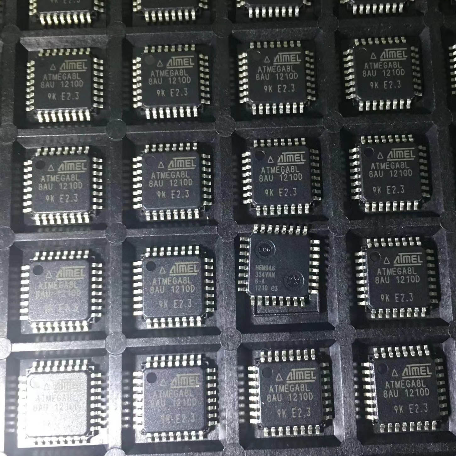
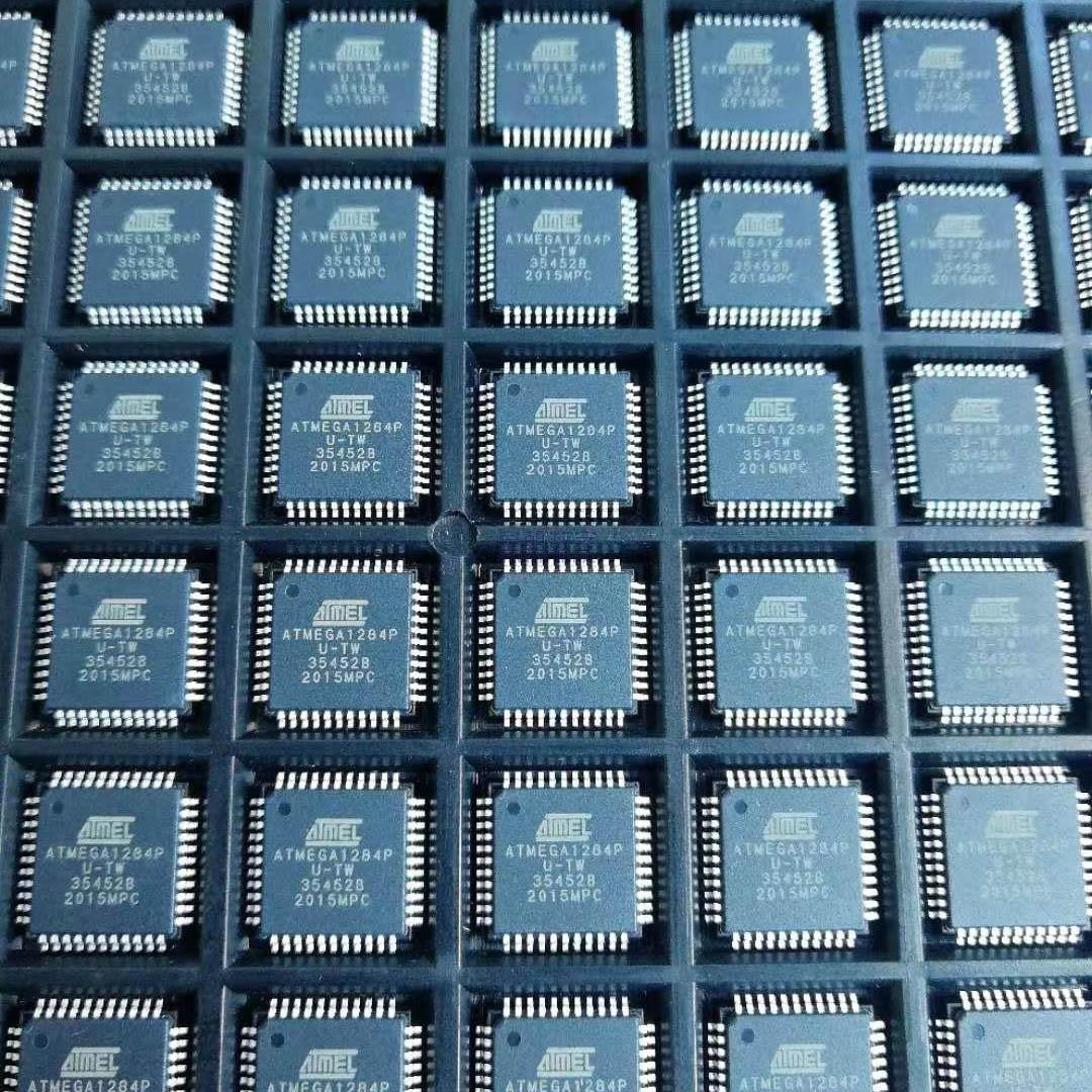
ATMEGA32 – 16AU
Microcontroller Core The ATMEGA32 – 16AU is based on an 8 – bit AVR microcontroller core. It comes with a comprehensive instruction set that includes arithmetic, logical, data transfer, and control instructions. This enables it to execute a wide range of tasks and operations, providing flexibility for programmers to develop applications for various requirements.
It operates at a maximum clock frequency of 16 MHz. The clock speed determines how quickly it processes instructions and performs internal operations, ensuring efficient interaction with external components and timely execution of tasks.
Memory Configuration Flash Memory: It features an internal Flash memory for program storage. The Flash memory has a capacity of 32 KB, which provides ample space for developers to store their application code. This non – volatile memory retains the programmed instructions even when the power is turned off, making it suitable for applications where code preservation is essential.
Data Memory: The internal data memory consists of 2 KB of SRAM (Static Random – Access Memory) and 1 KB of EEPROM (Electrically Erasable Programmable Read – Only Memory). The SRAM is used for temporary storage during program execution, such as holding variables and intermediate calculation results. The EEPROM is useful for storing data that needs to be retained even after power cycles, like configuration parameters or calibration values.
Input/Output Ports The microcontroller is equipped with four 8 – bit input/output (I/O) ports, namely Port A, Port B, Port C, and Port D. These ports together provide 32 I/O pins that can be configured as either input or output depending on the application’s needs.
Port A: Some pins of Port A have analog input functionality, allowing the microcontroller to interface with analog sensors and convert the analog signals into digital values for processing.
Port B: It has pins that can generate interrupts upon specific pin state changes, enabling the microcontroller to respond promptly to external events.
Ports C and D: These ports have their own unique characteristics and can be used to interface with a wide range of external components such as switches, LEDs, other microcontrollers, etc. The pins can be set to receive signals from external devices or send control signals to them.
Interrupt System It has a built – in interrupt system with multiple interrupt sources. These include external interrupts triggered by external pins and internal interrupts generated by events such as timer overflows, comparator outputs, or serial communication events. When an interrupt occurs, the microcontroller can suspend its current operation and jump to a specific interrupt service routine to handle the event.
The interrupt system assigns priorities to different interrupt sources. This ensures that more critical events are dealt with first, maintaining the orderly operation of the system and enabling efficient multitasking in response to various external stimuli.
Timer/Counter Units The ATMEGA32 – 16AU incorporates two 8 – bit timer/counter units and two 16 – bit timer/counter units. These can be used for a variety of purposes.
They can generate precise time delays. For example, in a time – controlled application, the timer/counter units can be used to wait for a specific period before performing a certain action.
They can measure the time interval between external events. In an event – counting application, they can count the number of events that occur within a specific time frame.
They can also create pulse – width modulated (PWM) signals. In applications such as motor control or lighting control, PWM signals generated by these units can be used to adjust the speed of a motor or the brightness of a light.
The timer/counter units can be configured in different modes, each offering distinct features and capabilities. They can operate in either timer mode (counting internal clock cycles) or counter mode (counting external events based on the input signals received at specific pins).
Analog – to – Digital Converter (ADC) It has a 10 – bit analog – to – digital converter. The ADC allows the microcontroller to convert analog input signals from sensors (such as temperature sensors, light sensors, etc.) into digital values. This enables it to interface with the real world more effectively and process analog information in a digital system. The ADC has a specific number of input channels and can be configured with different reference voltages and sampling rates according to the application’s needs.
Serial Communication The microcontroller supports serial communication through its USART (Universal Serial Asynchronous Receiver/Transmitter) module. This enables it to communicate with other devices that support serial communication protocols, such as PCs, other microcontrollers, or external peripherals. The USART can operate at different baud rates, which can be configured according to the communication requirements. Serial communication allows for the transfer of data in a sequential manner, bit by bit. It can be used for sending commands, receiving sensor data, or sharing information among different components in a system. For example, in a remote monitoring system, the microcontroller can use serial communication to send the measured data to a central monitoring station.
Power Management It has power management features that allow it to operate efficiently under different power supply conditions. It can enter different power – saving modes when appropriate. For example, it can lower its clock frequency or turn off specific peripherals to conserve energy while still maintaining the ability to respond to critical events.
It can operate within a specific range of power supply voltages, which provides flexibility in choosing the power source and integrating it into various power – supplied systems.


